Container networking has changed a bit compared to the past virtualization of virtual machine networks. In the past, virtual machine network virtualization had to simulate NIC devices and the hardware details of virtual network cards. In the container era, network virtualization will reuse more of Linux’s existed network devices, which can be routed at the third layer of the protocol stack without going through hardware simulation from the very bottom. Another issue is the scalability of the network. For example, the number of virtual network devices in the virtual machine era was not as many as in containers, and the on/off of virtual hosts was not as frequent. The second-layer network solution was more than enough for virtual machines, but it might not be enough for larger-scale container networks.
L2 Bridging: Joining the Broadcast Domain
Joining a second-layer network is relatively simple and almost self-discovering. Just connect the network endpoints to the broadcast domain via a bridge. The switch automatically broadcasts packets to newly discovered network endpoints. If the other endpoint responds, it is recorded in the address learning database (FDB), and then point-to-point communication can be done via MAC addresses.
Switches are afraid of port bridging loops, and Ethernet frames do not have TTL like IP packets, which have a limited life cycle and are not very afraid of routing loops. However, second-layer loops will forward frames endlessly. To avoid loops, switches generally implement the STP protocol, exchanging topology information to generate a universally recognized unique topology.
Linux has a bridge device that is roughly equivalent to a physical switch, with implementations of flooding, address learning, and STP. But there is a difference: switches can focus solely on forwarding, while Linux also needs to support the protocol stack above the third layer, including the socket stack. There is a detail here: Linux does not allow configuring an IP for network devices connected to the bridge device. This is because the network devices connected to the bridge device will blindly forward second-layer traffic to the bridge, and they are too busy to understand and respond to third-layer traffic, so configuring an IP is meaningless. So, the question arises: if the host’s network access device eth0 is connected to the bridge device and cannot be configured with an IP, how does the Linux host respond to socket traffic? In this case, you can configure the IP for the bridge device. The bridge device parses the third layer of received frames and substitutes for the eth0 device to handle the third-layer protocol upwards, which is equivalent to the bridge device having an implicit port connected to the third-layer stack of Linux.
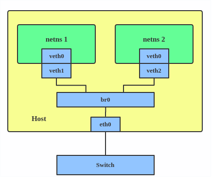
Using a bridge, you can create the simplest independent IP container network:

The container’s virtual network device can penetrate the namespace with a veth pair and then connect to the broadcast domain through the bridge. Once connected to the broadcast domain, it can declare its own IP by responding to ARP broadcasts.
macvlan & ipvlan L2
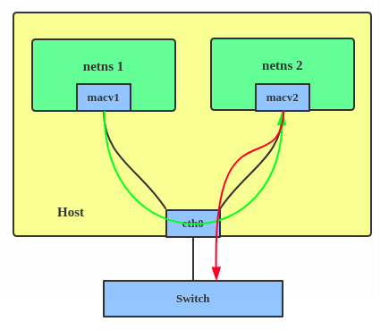
macvlan can be understood as a simplification of the bridge. This summary of macvlan is pretty good:
The macvlan is a trivial bridge that doesn’t need to do learning as it knows every mac address it can receive, so it doesn’t need to implement learning or stp. Which makes it simple stupid and and fast. ——Eric W. Biederman
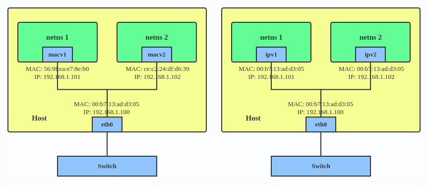
macvlan allows a single physical device to be divided into multiple virtual devices with independent MAC addresses. Since the addresses are known, there is no need for address learning, and since no loops are generated, there is no need for STP.

Single-port multi-MAC addresses may not be well supported in network environments, such as some switches having restrictions on the number of MAC addresses per port, which is uncontrollable for public cloud users.
ipvlan L2 slightly jumps to the second layer upwards, using the IP address as a marker to distinguish network devices, allowing multiple IP addresses behind a single MAC address.

The problems with L2 container networks are obvious:
- Large broadcast domain. If there are 100 physical machines with 100 containers each, the broadcast domain is 100 x 100 + 100;
- High jitter. The frequency of container on/off is incomparable to physical machines/virtual machines. Each change of a container will cause an ARP storm to all hosts’ containers;
- STP is designed to protect L2 networks from packet loop, but in extremely large L2 networks, STP itself can become a bottleneck;
L3 Routing
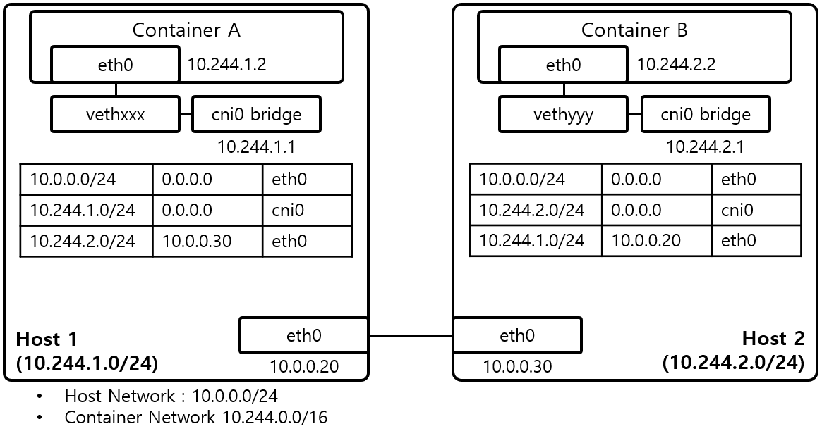
When L2 networks encounter scalability issues, the network must be divided into segments to isolate broadcast domains and communicate across segments via the IP protocol. A host within a segment does not need to care about the on/off of hosts outside the segment; it only needs to send packets to the router of the target segment.
The frequency of container on/off is high, but the frequency of physical machine on/off is much lower. The L3 container network solution is to treat physical machines as gateway segments, and the outside does not need to care about the on/off of containers within the segment. As for the on/off of the gateway, the routing table is synchronized through routing protocols or daemons running on the host. For example, in flannel’s host-gw mode, flanneld runs on each physical machine to listen for changes in the routing table in etcd and synchronize them to the local routing table:
